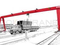
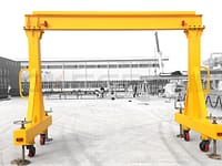
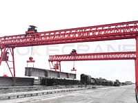
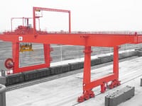
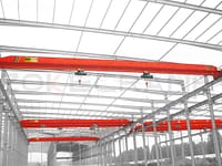
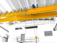
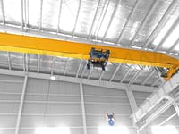
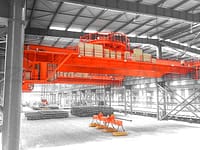
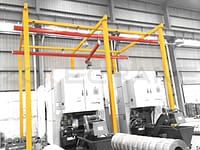
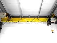
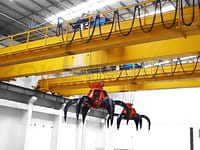
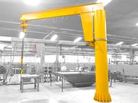
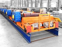
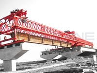
There are seven overhead cranes and gantry cranes, which are mainly used for lifting operations such as downsteaming, finishing treatment, outgoing and outgoing shipment, and auxiliary maintenance of equipment. Since the second half of 2020, bridge cranes and gantry cranes (QL12.5 +12.5t-31.5m-A6) in the process of large car operation, especially in the start, braking when the car body deflection, twisting and swaying, foreign sound significantly increased and other phenomena, and there have been several active wheel broken axle accident. In addition, there are bright traces on the side of the running track of part of the car, and there are burrs and deep groove-like abrasion marks in serious parts. There are bright spots and burrs inside the wheel rim of the big car. Preliminary analysis that these problems are mainly related to the operation of overhead cranes and gantry cranes to varying degrees between the wheel rim and track grinding tree, squeezing tight, due to the deterioration of the operation, the performance of the "nibble track". Failure if not dealt with in a timely manner, can lead to shorten the life of the track, may appear big car derailment, broken axle and other accidents, serious will cause irrecoverable damage to the track beam structure. After in-depth discussion, it was decided to adjust the wheels to improve the existing problems.


Measuring the horizontal and vertical tilt of the wheels
Before adjusting the wheels (Φ600mm) of the bridge-type heavy machine, firstly, the large wheel deflection was measured, including the horizontal and vertical tilt of the wheels. The method of measuring wheel horizontal tilt is as shown in the figure, taking the sliding line side as an example, first determine a datum line, pull a datum line with steel wire through the edge of I wheel and IV outer edge, and keep it parallel to the track, and measure the data of each point in turn with a steel plate ruler. Measure the vertical tilt of the wheel then use the wire pendant near the top of the wheel rim to hit a reference line, and use the steel plate ruler to measure the data of the corresponding points as shown in the table.
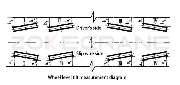

The measurement results showed that the horizontal tilt of the wheel of the IV wheel on the sliding line side was 10 mm, and the vertical tilt of the wheel of the I and IV wheels on the sliding line side was 5 mm (tilt outside the upper edge) and 10 mm (tilt inside the upper edge) respectively. The wheel tilt overlap is mainly caused by the processing error or improper installation position of the large wheel set and various undesirable factors in the use process.
Wheel adjustment
According to the measurement data, adjust the wheel that is out of tolerance. Use the jack to jack up the end beam of the wheel to be adjusted, and then add the appropriate thickness of shims for adjustment after the wheel is suspended. If the wheel position needs to be moved in the horizontal direction, cut off the shim plate and the bolt-mounted positioning plate, enlarge the bolt-mounted hole on the bending plate, and when the horizontal tilt and vertical tilt of the wheel and the span reach the requirements, then position the shim and the baffle plate for welding and complete the wheel adjustment.
The method of determining the shim thickness during the wheel horizontal tilt and vertical tilt adjustment is shown in the figure. When the wheel is deflected horizontally by θ, shims are added at the left vertical key to make δ' zero, and since θ' is small, there exists δ/d=δ'/r, and we can get δ=dδ'/r. Similarly, if the wheel is deflected horizontally in the opposite direction as shown in the figure, shims are added at the right vertical key to complete the adjustment. Wheel vertical deflection adjustment then add shims at the horizontal key, the calculation method is the same as the horizontal deflection adjustment method.
Adjustment, strict control of overhead cranes and gantry cranes wheel tilt in the standard range. Adjust the large wheel on the cab side and the slide line side respectively. Adjustment of the horizontal deflection of the big wheel is controlled within 1mm of L/800. 1mm of the vertical deflection of the big wheel is within L/400, and the upper edge of the wheel is tilted outside. In addition, control the wheel co-location difference on the same end beam, i.e. 2 wheels on the same end beam are controlled within 1mm, and any two wheels are controlled within 2mm.

Conclusion
Bridge crane and gantry crane wheel adjustment after an acceptance test passed. Put into use, the wheel contact with the track significantly improved, the sound reduction, eliminating the serious "nibble track" phenomenon. Comprehensive analysis, bridge cranes and gantry cranes bridge structure due to long-term full load operations, deformation of the main beam deflection, deflection of the main beam, etc. caused by a certain change in the wheel gauge, in addition, according to previous experience, by the operating environment, the large carriage track center distance, height difference, etc. are subject to further measurement and appropriate adjustment.
