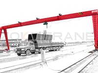
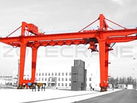
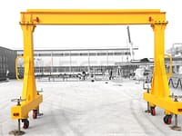
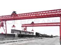
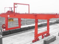
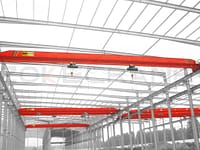
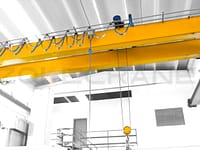
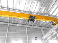
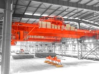
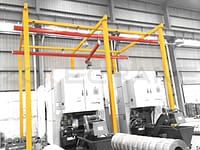
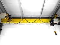
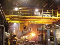
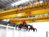
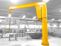
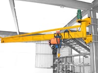
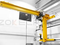
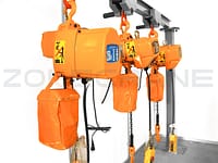
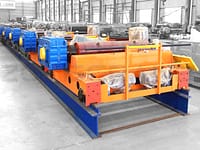
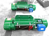
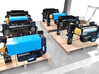
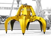
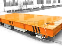
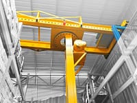
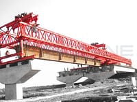
The 20 ton gantry cranes in this technical specification are mainly used for lifting and transporting large steel plates, section steels and other crane operations in the workshop.
Product name: 20t electromagnetic/hook semi-gantry crane
Working conditions: temperature -5℃-40℃, maximum relative humidity is 95%;
The service life of the steel structure is 30 years, the rest of the institutions guarantee 15-20 years, and the design life of the painting is guaranteed 5 years;
Power supply: AC 380V (±15%), 50HZ (±2%).

The main function, type and structure of the crane
Electromagnetic/hook semi-gantry cranes are mainly composed of trolleys, carts, steel structures, electrical equipment, etc.; steel structures are mainly composed of main beams, outriggers, lower beams, upper beams, and accessories. The main girder adopts a double main girder rectangular cross-section, and a flat track is laid on the main girder for the carriage to run. The outrigger adopts box-shaped variable cross-section, and the outrigger is connected with the main beam by flange bolts. There are a total of 8 walking wheels in the cart walking mechanism, and 4 walking wheels on each side of the track.
There should be a walking platform around the main girder of the crane, and the protective railings and protective plates should meet the corresponding standards.
The crane power supply adopts AC 380V 50Hz, the crane adopts trolley wire power supply; the trolley adopts flexible cables. The crane is also equipped with safety protection devices such as overload protection and limit positions of various mechanisms.
Main metal structure:
The metal structure is composed of main beams, outriggers, lower beams, hanging beams and other components.
The main girder is welded from plates into a rectangular cross-section. A diaphragm and angle steel are arranged inside the main girder to prevent the main girder from instability, and there are ribs under the laying track.
The main beam has an upward camber, which can be controlled at (1.1/1000~1.4/1000)S in the middle of the span. The maximum camber can be controlled within the range of S/10 in the middle of the span.
The outriggers are welded with a box-shaped structure, which is concise and clear in force, and has a beautiful and generous appearance; bolts are used to connect the outriggers and the lower beam, and between the outriggers and the main beam, which is convenient for disassembly and assembly.
The lower beam is welded with a box-shaped structure, with a simple and clear force, and a beautiful and generous appearance.
The trolley frame is a rigid member welded by section steel, steel plate, etc., and its full-load static deflection is less than L/2000, which fully guarantees the smooth operation of the upper mechanism. In addition to the upper part of the lifting mechanism and the trolley operating mechanism, corresponding settings This ensures that the driver and staff can reach any part of the trolley under any circumstances. A safety ruler is set on the side of the trolley frame, and the sufficient strength and rigidity of the trolley frame design ensure the assembly accuracy and performance of each mechanism.
The hanging beam is parallel to the main beam, and one end of the steel wire rope is fixed by an anti-rotation screw.
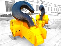
Two 10t hooks are set below the hanging beam.
The panel and diaphragm materials of the main beam, lower beam, leg, upper beam are Q235B, the internal steel stiffener material is Q235A, the welding rod is E4303 (GB5117), and the automatic welding wire is E501T-1.
The platforms, railings, ladders, etc. on the cranes are designed to be used as the passages for getting on and off the vehicle, and for maintenance and safety. They are designed and manufactured in accordance with the relevant safety regulations and design specifications. The width is greater than 500mm, and the walking platform adopts checkered plates with good anti-slip performance. It is safe to install a protective board with a height of not less than 100mm around the platform, a railing height not less than 1050mm, and two horizontal rails at a distance of 350mm.
Main institutions and facilities
Trolley lifting mechanism:
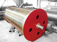
The lifting mechanism is composed of reel, reducer, brake, motor, coupling, compensation shaft, steel wire rope, hook and other components.
The reel shall be a coiled reel with a material of Q235B or higher. After relevant inspections, it shall have a quality certificate. The diameter and length of the reel shall meet the requirements that the wire rope can be left on the reel when the hook is at the lowest limit. The safety ring and fixing ring, the pressure plate and the fastening bolts shall be firm and reliable.
The hook material shall be steel DG20 that has undergone strict inspection and meets the national standard, and its manufacturing process shall meet the requirements of the specification, and shall have the corresponding quality certificate. Each hook should have a safety device to prevent the wire rope from falling off. The motor is a special frequency conversion motor for cranes, with a rated voltage of 380V, a frequency of 50Hz, and an insulation class of F.
The protection level is IP44.
The brakes are all hydraulic disc type, and the safety factor of each brake is not less than 1.75.
The reducer adopts steel plate welding form.
The wire rope adopts 6W (19) wire contact wire rope, which has compact structure, high strength and long service life, and it can safely meet the needs of normal crane work.
Trolley operating mechanism:
The running mechanism adopts a centralized drive, which is mainly composed of main components, a wheel set, and a three-in-one reducer.
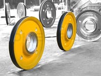
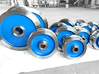
All parts and supporting equipment shall be high-quality and qualified products and meet the requirements of corresponding technical specifications. The wheel has a single rim. The wheels are forged parts, the wheels must be heat treated, the surface hardness reaches HB300~380, and the depth of 20mm is not less than HB260.
With spring buffer, it can quickly convert impact kinetic energy into elastic potential energy. It has the characteristics of good elasticity, fast recovery, impact resistance, etc., and is designed according to the full-speed operating state of the mechanism.
Crane trolley walking mechanism:
There are a total of 8 wheels in the cart running mechanism, with 4 wheels on each side. The wheels and wheel axles are made of high-quality and qualified materials. The driving mechanism is mainly composed of main and passive wheel sets, three-in-one reducers and other components. The trolley is driven by 1/2, and two sets of trolley drive mechanisms are installed in the whole crane.
The wheels have double rims. The wheels are forged parts, the wheels must be heat treated, the surface hardness reaches HB300~380, and the depth of 20mm is not less than HB260.
The two ends of the crane are equipped with a trolley limit device and a safety ruler, and the crane is forced to cut off the power when it is close to the rail terminal or other vehicles to protect the safety of related equipment.
The horizontal and vertical deflection of the wheels of the wheel set is strictly controlled within the specified range, and the phenomenon of rail gnawing is not allowed.
The cart, trolley and hoisting mechanism should have reliable braking system-level end-stroke limit devices and buffer devices.
The lubrication part of the crane adopts manual centralized lubrication.
Requirements for the electrical part of the crane
Trolley power supply: trolley wire power supply; in order to prevent the spreader or steel wire rope from colliding with the power cord when the trolley travels to the extreme position, a conductive wire stopper is installed under the two main beams of the bridge near the power supply.
Trolley power supply: use column processing steel and electrical cables to conduct electricity, traction wire ropes and shackles are made of stainless steel,
The structure is compact, safe and convenient to use. The cable is fixed on the middle pulley, and the middle pulley is hung under the I-beam, and the pulley slips with the movement of the trolley.
Working power supply AC 380V 50HZ three-phase four-wire.
The large and small vehicles, and the hoisting mechanism all adopt the frequency conversion speed regulation system.
Requirements for safety protection devices of cranes
The cable-powered crane adopts three-phase four-wire AC 380V power supply, and the power supply is supplied from the middle of the track.
The lighting and signal parts are equipped with a dedicated isolation transformer, the primary side incoming line voltage is AC 380V, and the secondary side outgoing line voltage is AC 220V, 36V. AC 220V is the power supply for crane lighting and maintenance power tools, and AC 36V is the power supply for crane safety signals and maintenance lighting. The necessary lighting fixtures should be installed under the main beam of the crane according to the span and the place of use.
The crane shall be equipped with indicating, monitoring and protection equipment, and the protection level of the electrical equipment shall not be less than IP54.
The lifting limit of the lifting mechanism is equipped with two protection devices, and the lifting limiter is set according to the requirements of the specification.
The lifting system adopts hydraulic push rod brakes, and the braking safety factor of each brake is not lower than the relevant standards. The crane should be protected by anti-slipping hooks. When the brake fails, the hanging parts should not slip the hooks.
A rail sweeper is installed in front of the big wheels; safety guards are provided for each movement mechanism, and the shaft must be covered.
Crane electrical appliances shall have the following protections (including but not limited to):
1.Short circuit protection, grounding protection, over current protection, loss of voltage protection, over voltage protection, rising limit protection, travel protection, emergency power off protection, zero protection. When the fault is restored, if the operating handle does not return to the zero position, each mechanism cannot start by itself.
2.The installation position of the limit switch of the cart should be reasonable, safe and reliable.
3.Safety switches are installed on the inclined ladder doors and railing doors of the bridge to enter the crane. When any door is opened, the safety switch is also disconnected, the main contactor is automatically disconnected, and all the crane mechanisms cannot be activated to ensure Safety of personnel on board.
4.The door into the driver's cab and the door from the driver's cab to the bridge frame are equipped with limit switches. When any door is opened, all mechanisms of the crane cannot work.
5.The suspension of the cab and below the main beam is a fully enclosed structure with good thermal insulation performance;
6.All necessary display and alarm devices such as power failure and overweight should be installed within the sight of the operator;
7.The cab is equipped with an air conditioner to make the cab reach a suitable temperature in different seasons;
8.A foot-controlled horn and wiper are installed in the cab.
9.The linkage platform uses domestic high-quality master handles to achieve gear speed adjustment, universal operation, and the handle automatically returns to zero to avoid misoperation. The master controller is used to control the start, speed, and stop of each mechanism.
Control form of electromagnet
Each electromagnet is required to be individually controllable and can be turned on or off at will; each electromagnet has an electromagnetic release function; the electromagnet is equipped with a general on and off switch; a magnetization switch is set; the electromagnet group requires a magnetization function. To ensure that the electromagnetic hoist can be used for multiple suction, single discharge and single suction; the display signal of the battery performance status is set on the cab; the electromagnet working voltage is 220V DC, three-phase full-wave rectification, and the connection duration is TD60 %; Insulation class is H; set up a power outage magnetism retention system, the power outage magnetism retention requirement of the electromagnetic crane is 15 minutes, and the magnetism retention system is absolutely safe and reliable, the power supply is connected to the lifting mechanism brake; the backup power supply uses maintenance-free storage batteries, The battery power system has automatic charging and detection functions.
Pretreatment and painting
The steel structure shall be sand washed or shot blasted before the first painting, and the rust removal level shall not be less than Sa2.5 level. The paint standard conforms to the GB9286 standard. The thickness of the Sa paint film is 25~35μm per layer, the primer is 85μm, the topcoat is 95μm, the total paint thickness is not less than 200μm, and the paint thickness in the steel beam is 75μm.
Painting: After the components are finished, they must be painted carefully. The primer is epoxy zinc-rich anticorrosive primer, the intermediate paint is epoxy six iron, and the top paint is double chlorinated rubber paint. The painting should be carried out in strict accordance with the painting process. Paint surfaces damaged due to various reasons should be repaired according to process requirements.
The color of the topcoat is orange-yellow.
