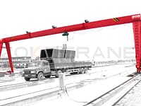
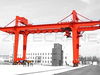
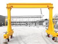
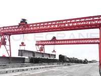
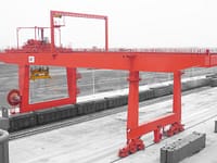
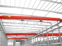
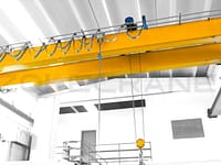
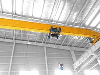
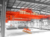
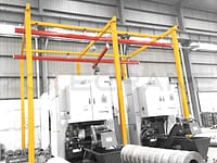
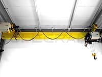
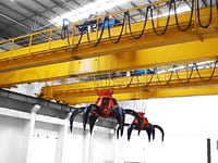
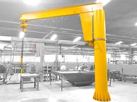
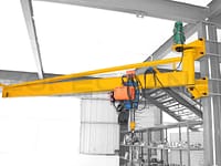
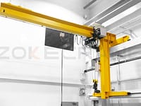
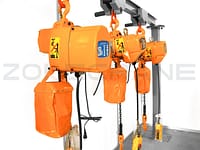
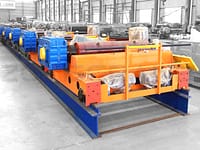
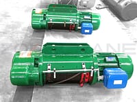
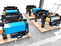
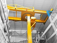
The electric hoist bridge crane works by moving along the direction of the plant track and the direction of the trolley track on the bridge, and the lifting movement of the hook.
Working environment conditions of electric hoist overhead crane
1. The power supply of the electric hoist bridge crane is three-phase four-wire AC, the frequency is 50Hz, and the voltage is 380V. The upper and lower limits of allowable voltage fluctuations on motors and electrical control equipment are ±10%, and the internal voltage drop of the crane is not more than 5%.
2. The installation of the running track of the electric hoist bridge crane should meet the requirements.
3. Electric hoist bridge cranes generally work indoors.
4. The grounding resistance of the running track of the electric hoist bridge crane is not more than 4Ω.
5. The altitude of the installation and use site of the electric hoist bridge crane does not exceed 1000m.
6. There should be no flammable, explosive, combustible dust and corrosive gas environment in the working environment.
7. The working environment temperature is -20℃~+40℃, the average temperature within 24h shall not exceed +35℃; the average temperature within 24h shall not exceed +25℃ and the relative humidity is allowed to be temporarily as high as 100% at +40℃ The relative humidity does not exceed 50%.
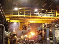
8. The electric hoist bridge crane is not suitable for lifting liquid metal or dangerous goods such as poisonous, flammable, explosive, and highly corrosive.
When users have different or special requirements for electric hoist bridge cranes, they can be negotiated separately and designed and manufactured separately.
Main performance parameters
Rated lifting capacity (t)
Electric hoist hook bridge crane: 3t, 5t, 10t, 16/3.2t, 20/5t, 32/5t, 50/10t, 75/20t, 100t. (Derived: 5/3.2, 5/5, 10/3.2, 10/5)
When the lifting weight is expressed as a fraction, the numerator represents the lifting weight of the main hook, and the denominator represents the lifting weight of the auxiliary hook.
Span (m)
10.5m, 13.5m, 16.5m, 19.5m, 22.5m, 25.5m, 28.5m, 31.5m.
Working level
Electric hoist bridge crane: According to the frequency of work and the load rate, it is divided into A5 (intermediate) and A6 (heavy).
Lifting height (m)
The lifting height of the electric hoist bridge crane is 3 meters and the maximum lifting height of various specifications is as follows: according to the determined lifting weight, span and working level, you can refer to the technical characteristics table and requirements in the random general drawing and the trolley general drawing The dimensions and weight of each part.

Structural features and working principle
Overall structure and work requirements
The whole crane is composed of four parts: bridge frame, trolley (hoisting mechanism equipped with operating mechanism and hook), crane operating mechanism and electrical equipment.
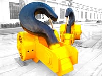
The lifting mechanism, the large and small car operating mechanism are all equipped with separate electric motors to drive their own. When the lifting capacity is 10t, it is a single hook crane with only one set of lifting mechanism. 20/5t, 32/5t, 50/10t, 75/20t cranes have two hooks, so there are two independent lifting mechanisms. The main hook is used to lift heavy objects, and the auxiliary hooks are used to lift lighter ones. In addition to the object, it can be used to coordinate the main hook to tilt or tip the object. However, two hooks are not allowed to lift two objects at the same time. Each hook can only lift objects whose weight does not exceed its own rated lifting weight when working alone. When two hooks are working at the same time, the weight of the object is not allowed to exceed Rated lifting capacity of the main hook.
Metal structure
The metal structure includes bridge frame, trolley frame and maintenance platform.
The bridge frame is composed of two box-shaped end beams, two box-shaped main beams and a platform outside the two main beams. Tracks are laid on the upper plane of the main beams for the carriage of trolleys. The running mechanism of the crane is installed on the walking platform outside of one main beam, and the conductive device of the trolley is installed on the outside of the other main beam. The outside of the walking platform is equipped with railings to ensure the safety of maintenance personnel during parking and maintenance. The main beam and the end beam are connected by bolts; it is detachable for easy transportation and installation.
The trolley frame is equipped with a trolley running mechanism and a lifting mechanism.
The electric hoist bridge crane is inspected and repaired on the auxiliary walking platform of the main girder. There are maintenance racks under the auxiliary walking platform of the main beam on the sliding line side, which can inspect and repair the power supply of the crane, and facilitate the power off and maintenance of the crane.
Crane operating mechanism
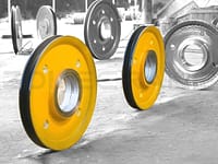
The crane operating mechanism is driven separately, with two or four sets of symmetrical and independent drive devices. The driving part adopts a three-in-one geared motor.
Lifting mechanism
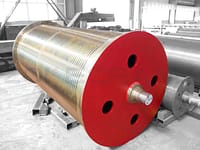
The electric hoist hook crane is equipped with a lifting mechanism on the upper part of the trolley frame. In the case of a single hook, it is a set of independent fixed electric hoists; when it is double hook, there are two sets of independent fixed electric hoists. The lifting mechanism adopts a fixed electric hoist.
Trolley operating mechanism
The running mechanism of the trolley is separately driven by a three-in-one reduction motor.
Crane inspection
Before the crane test operation, it is necessary to check whether the forward and reverse directions of the motor meet the requirements, adjust the gap between the brake shoe and the brake wheel (if it is a cone motor, adjust the axial movement of the cone motor), and check each reducer Whether there is oil inside, whether the oil passages of the lubrication points and oil pipes are unblocked, test operation can be carried out under normal conditions. According to the operating rules, the crane is powered on and enters the pre-rotation preparation state.
No-load test of crane
1. Turn on the power, start the various mechanisms, make the trolley run back and forth along the full length of the main beam, and check whether there is any jamming.
2. Start and check other mechanisms, check whether they are operating normally, whether the control system and safety devices meet the requirements and are sensitive and accurate, and check the lifting height and the left and right limit positions of the hook.
3. The empty hook is raised and lowered, and the lifting mechanism is activated to make the empty hook rise and fall several times. The action of the limit switch of the lifting mechanism should be accurate and reliable.
4. When the trolley is driven to the middle of the span, the crane travels twice along the full length of the plant at a slow speed, and then travels back and forth three times at the rated speed. When starting or braking, the wheels should not skid, the walking should be stable, the limit switch should be correct, and the buffer should work.
Static load test of crane
Stop the trolley in the middle of the main girder, and gradually load it to 1.25 times the rated lifting capacity, increase the load by 100~200mm from the ground and hang it in the air for 10 minutes, and then check whether the main girder is permanently deformed after unloading.
Repeat this three times, the main beam is allowed to have a little deformation in the first and second times, and the main beam shall not be permanently deformed in the third time.
After the test, the trolley was driven to the end of the main beam to detect the actual upward camber in the span of the main beam.
Static rigidity test of crane
After the static load test, stop the unloaded trolley at the span end of the main girder, use theodolite or other instruments to measure the vertical direction data of the datum point of the main girder mid-span, and then drive the trolley to the mid-span lifting rated load of the main girder. After the ground is 100~200mm, measure the vertical direction data of the reference point. The relative difference between the two data is the static rigidity of the crane.
Dynamic load test of crane
During the dynamic load test, there should be a gap time according to the connection duration rate, and control according to the operating regulations, and the acceleration, deceleration and speed must be controlled within the normal working range, and the test should be 1.1 times the rated lifting capacity.
The dynamic load test of each mechanism of the crane shall be carried out separately, and then a joint action test shall be performed, and the two mechanisms shall be activated at the same time (but the main and auxiliary hooks shall not be activated at the same time). In the test, each action should be repeatedly started and braked in its entire operating range. According to its working cycle, the test time should last at least 1h.
If in the test each component can complete its function test, when the suspended air load is lifted in the air, the test load does not show reverse action, and in the subsequent visual inspection, check whether the mechanism and structural members are damaged , Whether the connection is loose or damaged.
Crane maintenance and protection
In order to ensure the normal use of heavy machinery and prolong the service life of parts, components and cranes, regular maintenance and maintenance must be carried out on them. According to the importance of each component and structure, the difficulty of ensuring safety, the frequency of use, the wear and tear of components, etc., the inspection cycle of each component or location is specified.
Transport and storage
1. The water and land transportation of our factory is convenient, and we can arrange consignment for users.
2. After the crane arrives at the site, first check the parts and components according to the packing list, and then check the technical documents according to the random drawing catalog.
3. Check whether the bridge and other objects are damaged or deformed during transportation. If deformation occurs, try to eliminate it.
4. If the crane is temporarily not installed. When storing, it should be placed steadily, and ties should be symmetrically laid flat and cushioned. The storage floor should be strong to prevent the bridge from sinking over time and causing deformation of the bridge frame. When stored in the open air, sheltering measures must be taken to protect it.
5. If you find any problems or have any questions, please contact our factory's user service team in time.
